Services
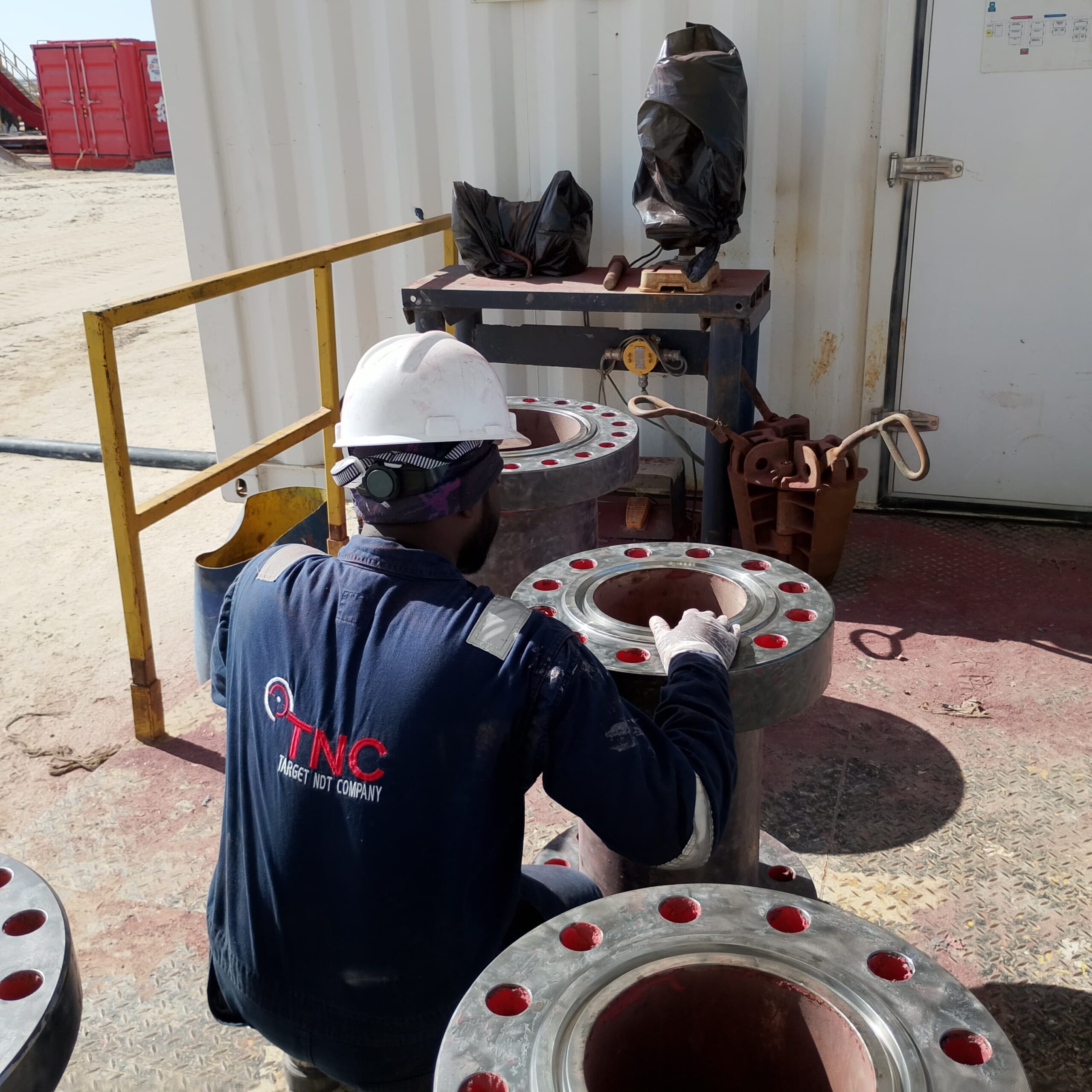
Visual Testing (VT) & Dimensional Inspection
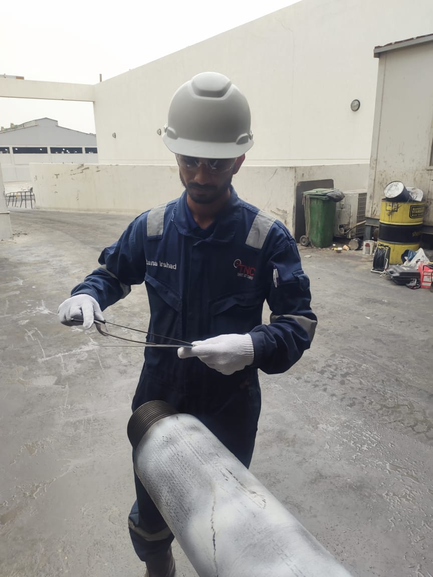
VT is the primary NDT method for detecting surface discontinuities using the naked eye, supported as needed by optical aids (magnifiers, boroscopes, mirrors) and remote-viewing equipment. If a component is accessible for viewing, VT is performed first to identify surface defects and areas requiring further assessment.
- Tool joint outer diameter (OD) and inner diameter (ID)
- Box shoulder width
- Tong space
- Box swell measurement
- Counterbore depth
- Pin lead and bevel diameter
- Box seal width
- Shoulder flatness
- Full dimensional inspection of rotary shouldered connections
- Thread profile measurement
- Standoff checks, lead assessment, and taper verification
Dimensional Inspection
Dimensional inspection verifies critical geometry on tubulars and BHA to ensure fit, strength, and safe operation per DS-1 Latest Edition, API RP 7G-2, and NS-2 standards.
OD & ID Gauging
Full-length caliper gauging measures outer diameter (OD) for wear, dents, mash marks, slip damage, and ovality, while ID checks bores for straightness and obstructions.
Thread & Connection Inspection
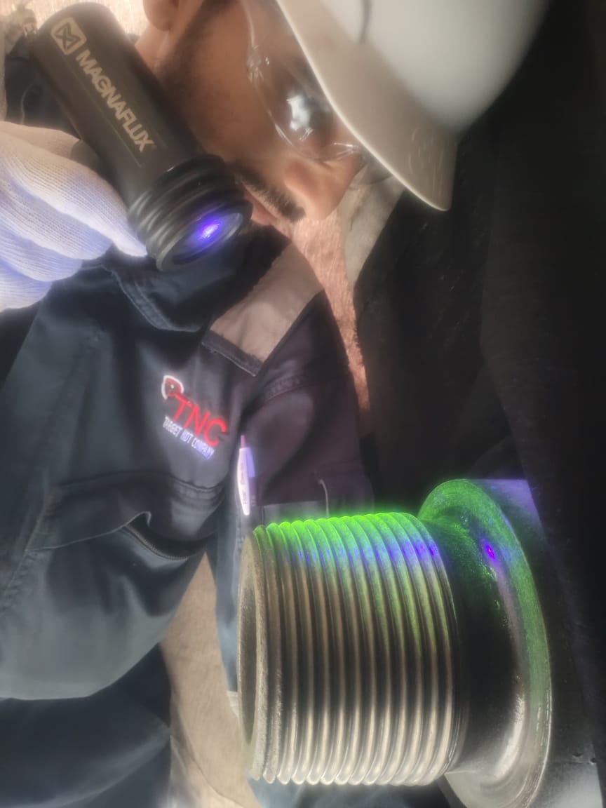
Thread gauging uses taper, lead, height gauges for pin/box fit per API/DS-1; visual/blacklight checks for galling, cracks, dope condition. Rotary shoulder connections (RSC) get UT-RSC for shoulder flatness and shoulder engagement (SE).
Drifting
API/special drifts (mandrels) run full-length to confirm ID clearance for tools/bits; obstructions marked and reported. Ensures no mashes/dents block passage, critical for Casing and Tubing, drill pipe and collars.
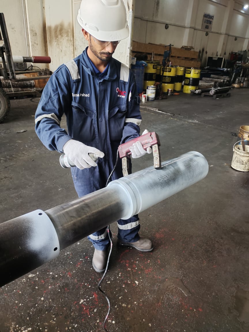
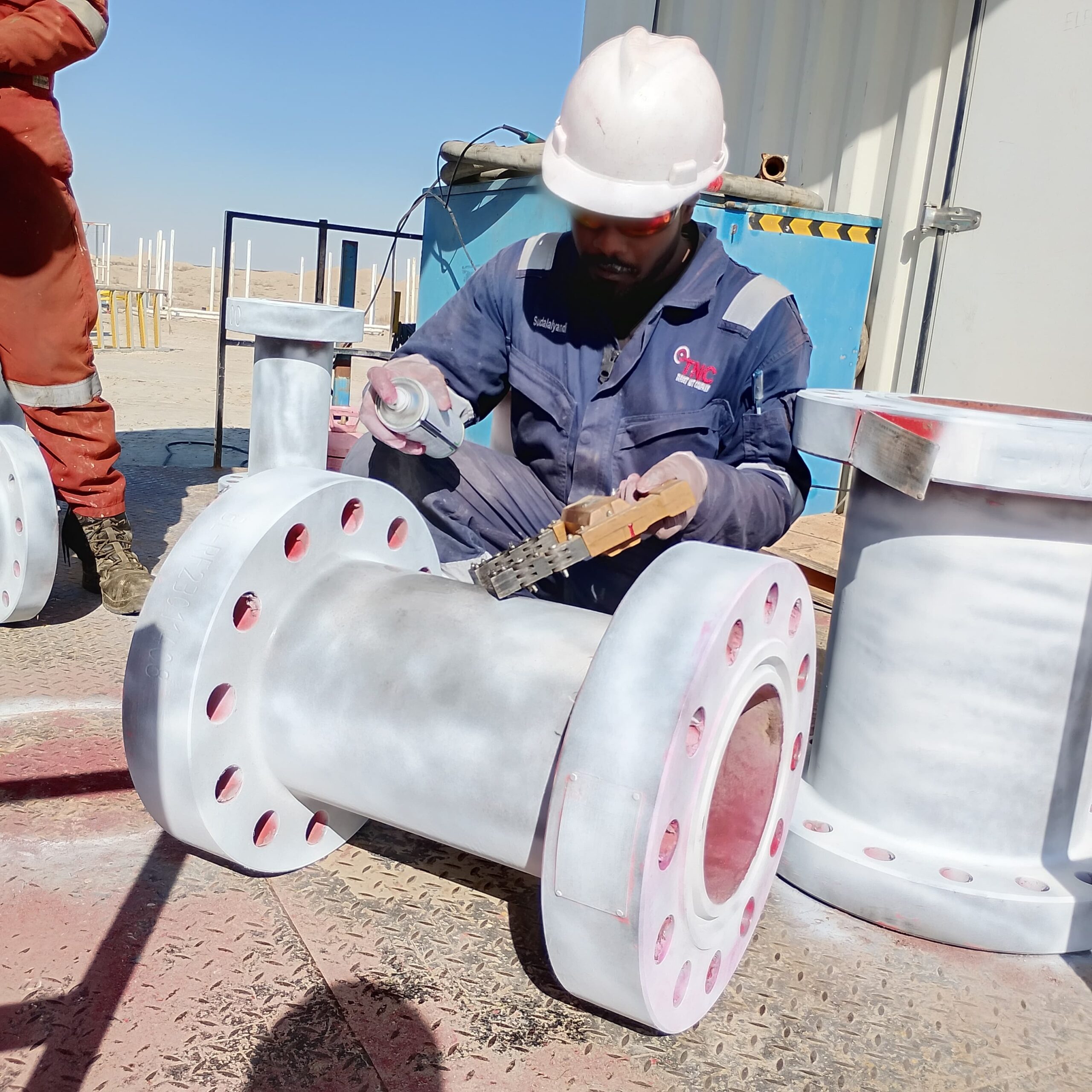
Magnetic Particle Inspection (MPI)
Scope
MPI is used to detect surface and near-surface discontinuities in ferromagnetic materials (iron, nickel, cobalt alloys, etc.).
Principle
A magnetic field is induced in the test object. Discontinuities cause magnetic flux leakage at those locations; ferrous particles accumulate at flux-leakage sites and reveal indications.
Magnetization methods
API/special drifts (mandrels) run full-length to confirm ID clearance for tools/bits; obstructions marked and reported. Ensures no mashes/dents block passage, critical for Casing and Tubing, drill pipe and collars.
- Direct (longitudinal) magnetization: electric current is passed through the part, producing a magnetic field within the material.
- Indirect (circumferential) magnetization: an external magnetic field is applied without passing current through the part; magnetic field lines are oriented relative to the applied field.
- Particle application: Ferrous particles are applied as dry powders or wet suspensions (visible or fluorescent under UV) to reveal indications at leak sites.
- Indication evaluation: Indications are assessed to characterize the feature (type, size, orientation), determine probable cause, and recommend disposition or further action.
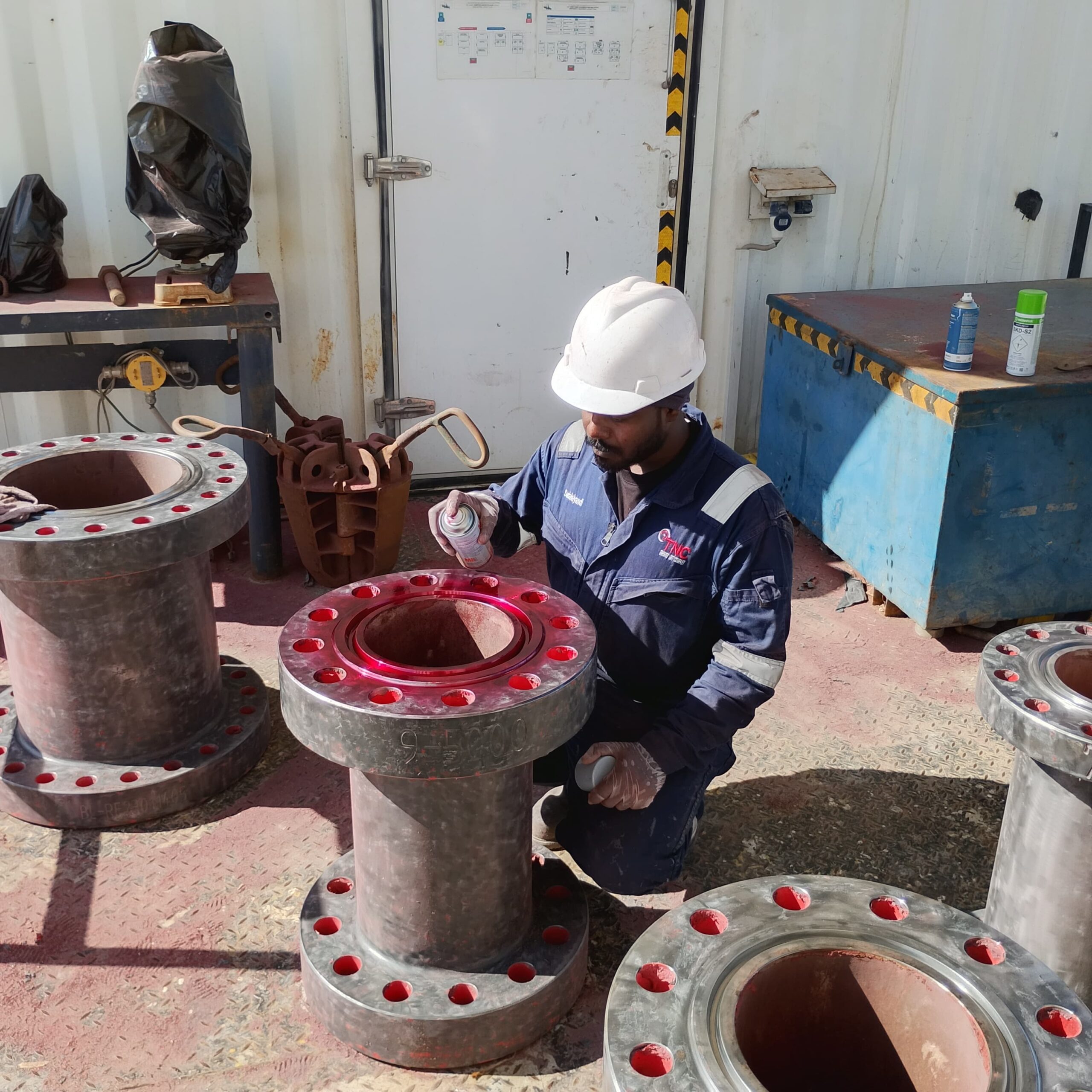
Liquid Penetrant Testing (LPT)
Dimensional inspection verifies critical geometry on tubulars and BHA to ensure fit, strength, and safe operation per DS-1 Latest Edition, API RP 7G-2, and NS-2 standards.
Scope
LPT locates surface-breaking defects in non-porous materials (metals, ceramics, glass, some plastics). It is widely used for castings, forgings, welds and in-service components to find surface porosity, hairline cracks, leaks, and fatigue cracks.
Principle
A low-viscosity penetrant is applied to the surface and drawn into surface-breaking discontinuities by capillary action. After a prescribed dwell time the excess penetrant is removed, a developer is applied to draw out penetrant from flaws, and indications are evaluated visually (under white light or UV for fluorescent systems).
When to use
LPT is ideal for detecting surface defects. For ferrous components where subsurface detection is required, Magnetic Particle Inspection is often preferred.
Processes offered
LPT is ideal for detecting surface defects. For ferrous components where subsurface detection is required, Magnetic Particle Inspection is often preferred.
- Visible dye penetrant (water-washable, solvent-removeable)
- Fluorescent penetrant (UV inspection)
- Water-washable and solvent-removable formulations to suit part condition and production needs
Ultrasonic Testing (UT) / Wall Thickness / Hardness Testing
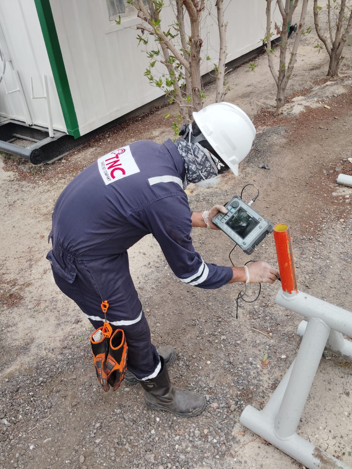
Conventional Ultrasonic Testing (UT), shear wave UT, and ultrasonic wall thickness gauging are complementary nondestructive testing methods used mainly for flaw detection and thickness/corrosion evaluation in pipes, tubes, and welds. Micrometer measurement is a simple mechanical method used mainly on exposed pipe ends to confirm wall thickness where both sides are accessible.
Conventional Ultrasonic Testing
Conventional UT uses a single probe to send highfrequency sound into the material and measure echoes from flaws or backwall surfaces to determine defect location and thickness. This method is widely used to trend material loss over time in corrosion and erosion monitoring programs, supporting planned remediation and preventative maintenance.
Shear Wave Ultrasonic Testing
Shear wave (anglebeam) UT introduces the beam at an angle using a wedge so that shear waves intersect weld fusion lines and heataffected zones where planar flaws tend to occur. As the probe is moved along the weld, changes in reflected signals are used to detect, locate, and size weld discontinuities such as lack of fusion and cracks.
Ultrasonic Wall Thickness Measurement
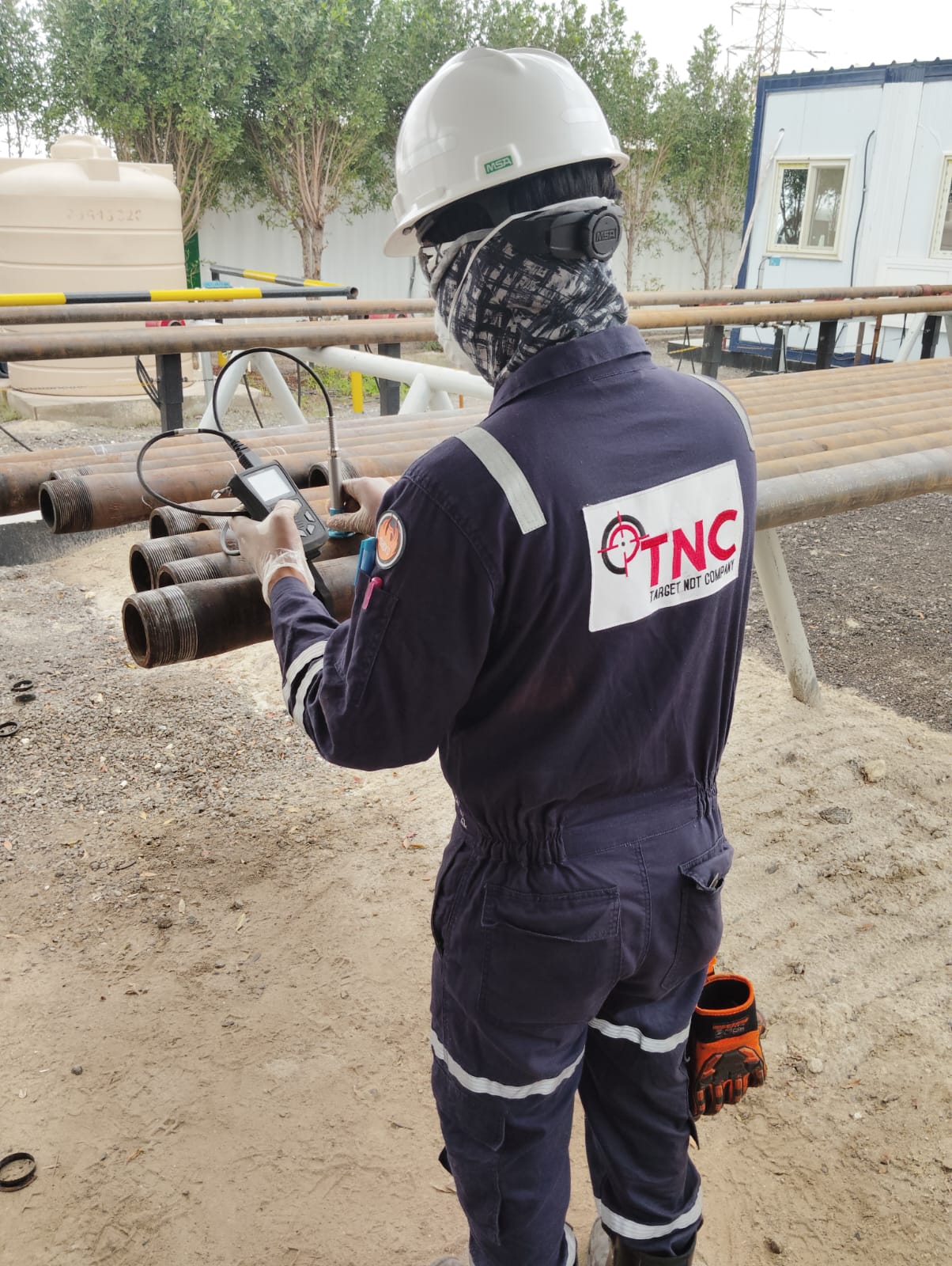
Ultrasonic wall thickness gauges calculate thickness from the timeofflight of an echo between the front and back wall, using the known sound velocity in the material. Modern gauges can perform multiple circumferential readings to establish minimum and maximum wall thickness in a given area for corrosion mapping and life assessment.
Micrometer Measurement
Micrometers provide direct mechanical thickness readings where the component end or coupon is accessible from both sides and surfaces are reasonably flat. They are commonly used on plainend pipe or cut samples to verify nominal wall thickness and to calibrate or crosscheck ultrasonic thickness readings.
Ultrasonic Wall Verification
Wall verification with UT is the practice of confirming that the tube or pipe body meets specified nominal wall requirements without cutting or sectioning the component. By combining spot checks and circumferential scans, this verification supports both initial quality control and inservice integrity assessments for pressure parts and piping systems.
EMI- Electro Magnetic Inspection
Computerized EMI is well suited to detecting changes that affect the magnetic or electrical response of the pipe body. Typical detectable conditions include:
- Cuts, gouges, and mechanical damage on the outside surface.
- Outside diameter (O.D.) wear, corrosion pits, and general wall loss.
- Longitudinal and transverse cracks, fatigue damage, and laminations.
- Diameter variations, dents, ovality, and local expansions or restrictions (often via integrated caliper or geometry channels).
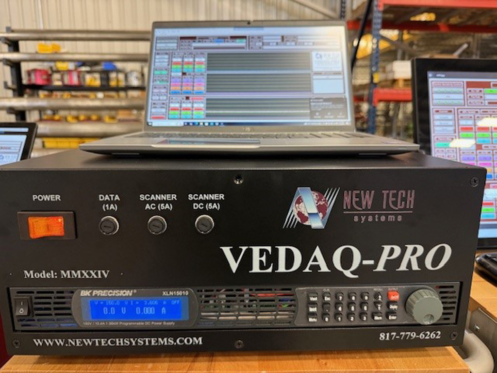
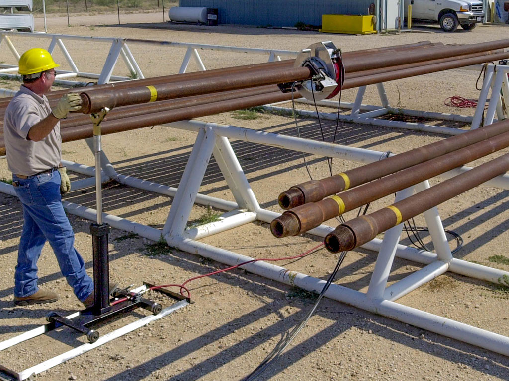
A typical EMI unit consists of a solidstate electronics console, magnetizing or excitation coils, and an array of Halleffect or similar magnetic/electromagnetic sensors arranged around the pipe circumference. The pipe is driven through the inspection head, where it is magnetized or subjected to an alternating electromagnetic field, and disturbances caused by defects are picked up by the sensors and processed in real time by the computerized system.
Role of Hall Sensors and SolidState Electronics
Modern systems use advanced Halleffect sensors and digital signal processing to achieve high sensitivity and noise rejection. This improves resolution for small pits and tight cracks, enables higher inspection speeds, and provides stable calibration and electronic traceability for quality records.
Multi-Function EMI (Transverse and Longitudinal Defects)
“4function EMI” usually refers to a multichannel configuration that combines different magnetizing and sensor arrangements to reveal flaws of different orientations and types. In the context you gave, it specifically includes functions dedicated to: Detection of longitudinal defects running parallel to the pipe axis (e.g., seam flaws, longitudinal cracks). Detection of transverse defects running circumferentially across the pipe (e.g., crosscracks, tool marks), along with channels for wallloss and general body defects
Eddy Current Inspection
Eddy current testing (ECT) is a non-destructive electromagnetic method used on electrically conductive materials to assess surface and near-surface conditions without causing damage. It is particularly useful because it can be performed quickly, often without direct contact or couplant, and can be automated for highspeed inspection.
- A coil carrying alternating current generates a changing magnetic field, which induces circulating “eddy” currents in the conductive test piece.
- Discontinuities or changes in material properties disturb these currents, causing measurable changes in coil impedance that are displayed and interpreted by the instrument.
Main applications
Flaw detection: Detection of surface and nearsurface cracks, laps, porosity, and other discontinuities in components such as aircraft structures, wheels, bars, tubes, and heat exchanger tubing.
Material and coating thickness: Measurement of nonconductive coating thickness (paint, anodizing, etc.) on conductive substrates, and thin metallic layers in some configurations.
Material identification: Differentiation of alloys and grades based on electrical conductivity and permeability, useful for sorting mixed materials.
Heat treatment verification: Assessment of heat treatment condition and hardness because conductivity and magnetic properties change with heat treatment state (e.g., case depth, tempering).
Portable Refacing
- Restore minor galling, dents, corrosion marks, or light scoring on rotary shouldered connection faces so the shoulder can again provide proper metal-to-metal sealing and torque transfer.
- Reduce nonproductive time and cost by allowing multiple light refacing operations in the field before a full re-cut is required in a machine shop.
- The refacing tool is clamped or located on the pin or box so that its cutting/emery surface runs square to the connection axis.
- The operator energizes the electric drive and applies controlled pressure so that only a small amount of metal is removed, just enough to clean and flatten the sealing shoulder.
Quality and limits of repair
- After refacing, the shoulder is checked for flatness with a straightedge and for squareness to the axis, and the remaining material is verified against applicable benchmarks or limits.
- Field refacing is intended only for minor damage; if cumulative metal removal exceeds specified limits or if damage is severe, the connection must be re-cut or reconditioned in a machine shop.
Demagnetization of Ferromagnetic Materials
Demagnetization is required after magnetic inspection because residual magnetism can interfere with both equipment operation and future maintenance or welding quality. Leaving parts magnetized allows them to attract loose metallic particles, which can cause jamming, wear, and contamination in operating mechanisms.
Why demagnetization is needed
- Magnetized parts attract filings, grinding dust, and chips that may remain in housings, bearings, or hydraulic/mechanical systems, increasing the risk of abrasion, sticking, or malfunction.
- In welded or rotating components, residual magnetism can also disturb welding arcs or affect sensor readings in later inspections, reducing reliability and service life.
Typical demagnetization practices
- After magnetic particle or electromagnetic inspections, components are exposed to a controlled decreasing magnetic field (often AC or DC with gradually reduced current) to randomize magnetic domains and reduce residual field strength to an acceptable level.
- Residual magnetism is then checked with a Gauss meter, and parts are only returned to service when readings fall below specified limits, minimizing the risk of attracting debris during operation.
Lifting & Equipment Inspection
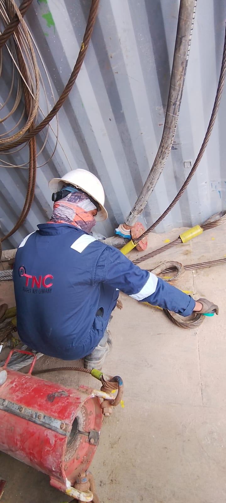
Lifting and equipment inspection services ensure safe operation of cranes, hoists, slings, rigging gear, and related machinery in Kuwait’s oil and gas sector through periodic thorough examinations, NDT, load testing, and certification.
Standards and Compliance
Oil/gas lifting inspections follow LEEA guidelines, API specifications, LOLER/PUWER principles, and local KOC/QP requirements, with frequencies of 6-12 months or after repairs. Certifications verify compliance with ISO/IEC 17020, EIAC/ENAS accreditation, and manufacturer specs; records include test logs and traceability.
Inspection Methods
Services cover visual checks for wear/deformation, NDT (MPI, UT) on pins/welds, proof load testing, and functional tests on controls/safety devices. Specialized oilfield focus includes wire rope EMAG, pedestal/offshore cranes, and explosion-proof gear.
Mobile equipment inspection
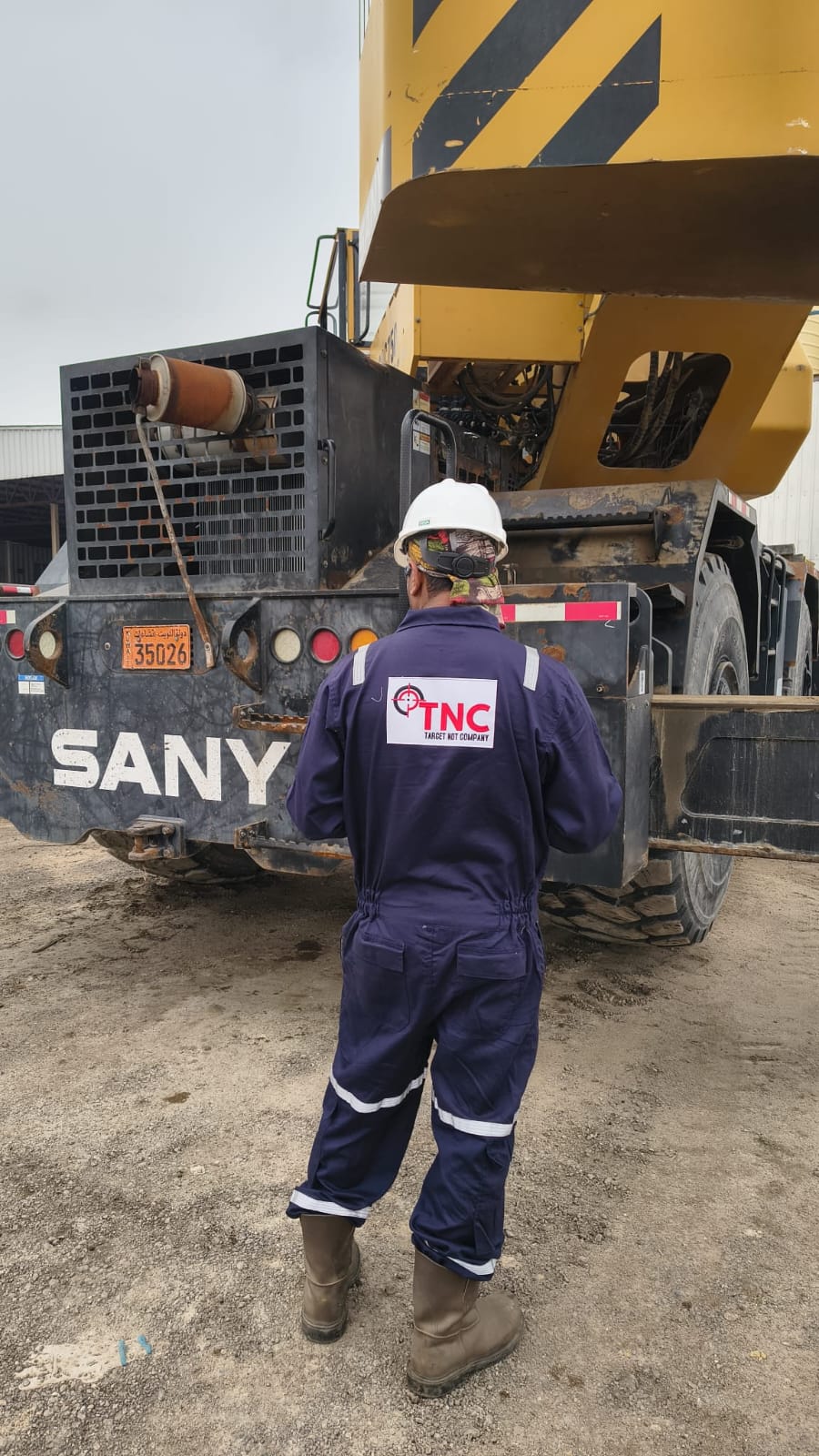
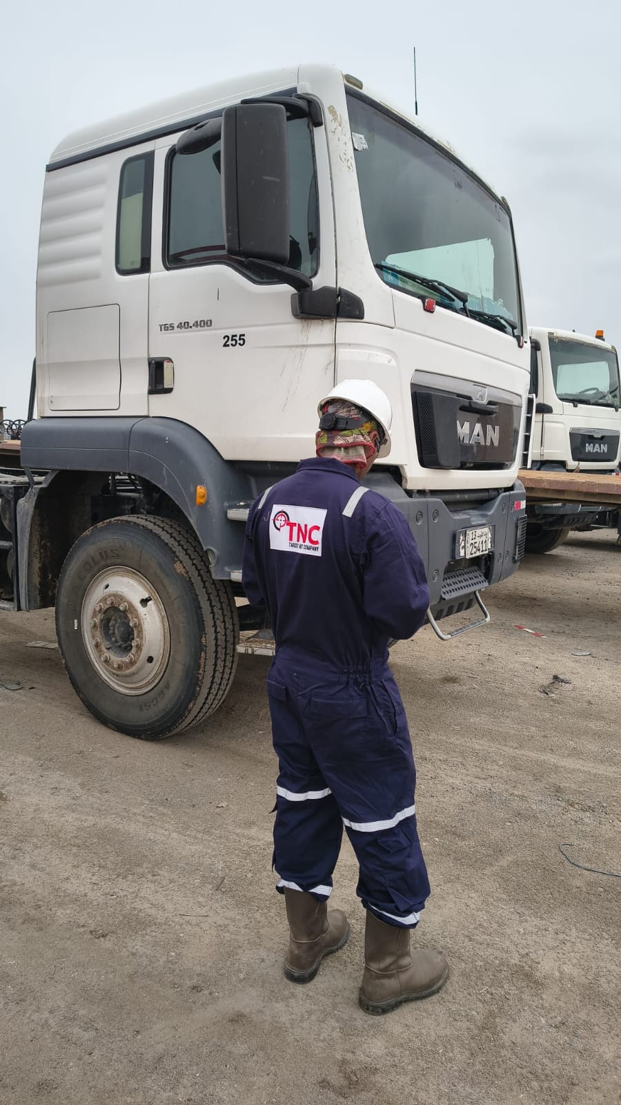
Mobile equipment inspection in Kuwait’s oil and gas sector verifies the safety and operational integrity of vehicles and machinery like cranes, forklifts, tankers, and earth-moving equipment through visual, functional, NDT, and load testing per LEEA, API, and KOC standards.
Scope and Standards
Inspections cover fuel/water/vacuum tankers, frac units, cementing units, trailers, generators, and mobile cranes, ensuring compliance with international codes, manufacturer specs, and local regulations like KOC HSE requirements. Frequency is typically annual or after major repairs, with digital certification and tagging.
Key Inspection Elements
- Visual/Structural: Frame cracks, weld integrity, tire wear, leaks, corrosion on tanks/chassis.
- NDT: MPI/UT on critical welds, pins, axles for fatigue/sub-surface flaws.
- Functional/Load Tests: Brakes, hydraulics, steering, lifting capacity (125% SWL for cranes); engine/compressor checks.
- Safety Systems: Lights, alarms, emergency stops, fire suppression, DROPS surveys
DROPS Survey & Risk Mitigation
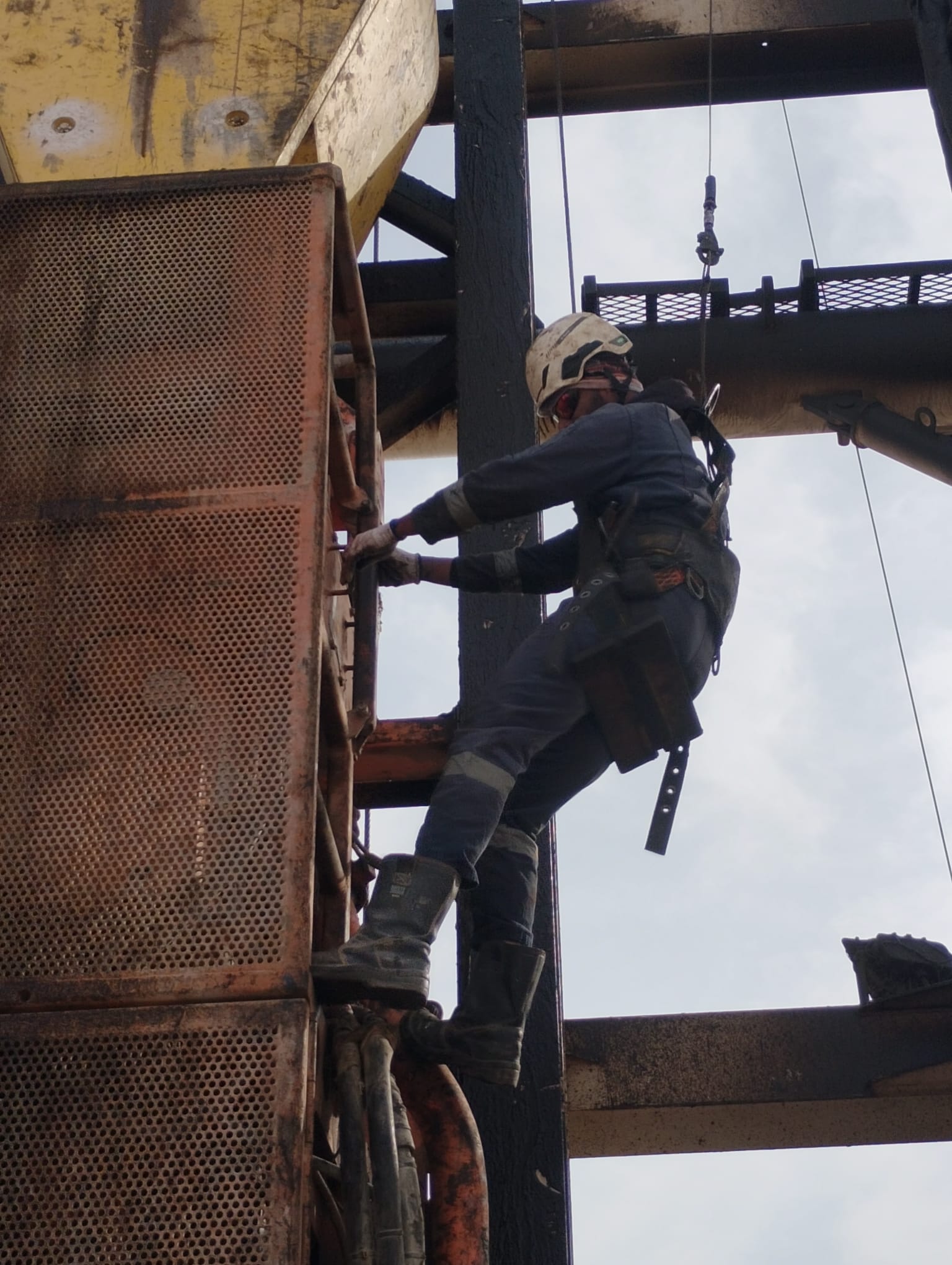
DROPS (Dropped Objects Prevention Scheme) surveys on drilling rigs systematically identify and mitigate risks from unsecured equipment, tools, or materials at height that could fall and cause injury, equipment damage, or downtime. These surveys follow industry guidelines like IADC HSE Section 16, DROPS Recommended Practice, and API RP 54, with independent third-party audits recommended quarterly or after high-risk operations like jarring.
Survey Process
DROPS surveys divide the rig into zones (derrick, substructure, pipe racks, monkey board) for systematic visual inspections of permanent and temporary equipment at height. Inspectors check for loose bolts, unsecured tools, degraded lanyards, and retention failures, using checklists, photos, and a DROPS register to log findings, priorities (critical/major/minor), and closeout actions.
Key Risk Areas on Drilling Rigs
- Derrick/Monkey Board: Top drive, elevators, tongs, spare parts, cameras—must use dual barriers (primary retention + tether/secondary catch).
- Rig Floor/Substructure: Pipe handling tools, kelly, stands, catwalk equipment prone to vibration loosening.
- Pipe Racks/Catwalks: Unsecured tubulars, elevators, slips during roughnecking or rough seas.
- Temporary Equipment: Hoses, gauges, cameras installed without engineering review or lock-wiring.
Risk Mitigation Measures
- Red Zones: Barricade high-risk areas under overhead work; permit-to-work system enforces no-entry during jarring/drilling.
- Tool Lanyards & Barriers: All tools at height tethered (min 2:1 safety factor); secondary catch nets/screens on critical paths.
- Inspections: Daily/weekly rig crew checks + monthly PM + quarterly independent DROPS survey; post-jarring/vibration inspections mandatory.
- Design & Maintenance: Lockwire/Nyloc nuts, DROPS-rated toolkits, equipment registers for temporary installs.
Visual Testing (VT) and Visual Dimensional Inspection
VT is the primary NDT method for detecting surface discontinuities using the naked eye, supported as needed by optical aids (magnifiers, boroscopes, mirrors) and remote-viewing equipment. If a component is accessible for viewing, VT is performed first to identify surface defects and areas requiring further assessment.
Tool joint outer diameter (OD) and inner diameter (ID)
Box shoulder width
Tong space
Box swell measurement
Counterbore depth
Pin lead and bevel diameter
Box seal width
Shoulder flatness
Full dimensional inspection of rotary shouldered connections
Thread profile measurement
Standoff checks, lead assessment, and taper verification
Dimensional Inspection
Dimensional inspection verifies critical geometry on tubulars and BHA to ensure fit, strength, and safe operation per DS-1 Latest Edition, API RP 7G-2, and NS-2 standards.
OD & ID Gauging
Full-length caliper gauging measures outer diameter (OD) for wear, dents, mash marks, slip damage, and ovality, while ID checks bores for straightness and obstructions.
Thread & Connection Inspection
Thread gauging uses taper, lead, height gauges for pin/box fit per API/DS-1; visual/blacklight checks for galling, cracks, dope condition. Rotary shoulder connections (RSC) get UT-RSC for shoulder flatness and shoulder engagement (SE).
Drifting
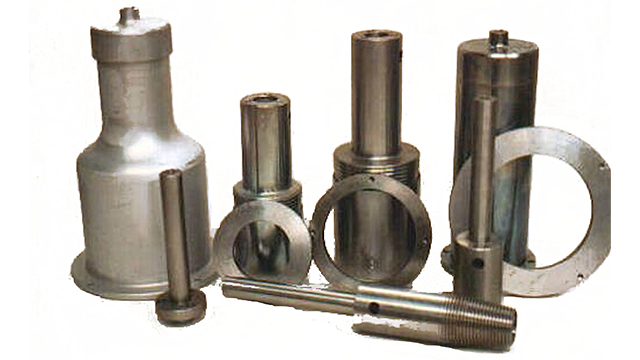
API/special drifts (mandrels) run full-length to confirm ID clearance for tools/bits; obstructions marked and reported. Ensures no mashes/dents block passage, critical for Casing and Tubing, drill pipe and collars.
Magnetic Particle Inspection (MPI)
- Scope: MPI is used to detect surface and near-surface discontinuities in ferromagnetic materials (iron, nickel, cobalt alloys, etc.).
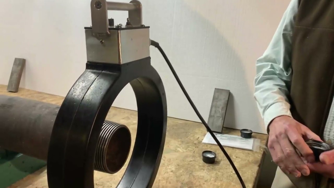
- Principle: A magnetic field is induced in the test object. Discontinuities cause magnetic flux leakage at those locations; ferrous particles accumulate at flux-leakage sites and reveal indications.
Magnetization methods
Direct (longitudinal) magnetization
electric current is passed through the part, producing a magnetic field within the material.
Indirect (circumferential) magnetization
an external magnetic field is applied without passing current through the part; magnetic field lines are oriented relative to the applied field.
Particle application
Ferrous particles are applied as dry powders or wet suspensions (visible or fluorescent under UV) to reveal indications at leak sites.
Indication evaluation
Indications are assessed to characterize the feature (type, size, orientation), determine probable cause, and recommend disposition or further action.
Liquid Penetrant Testing (LPT)
Dimensional inspection verifies critical geometry on tubulars and BHA to ensure fit, strength, and safe operation per DS-1 Latest Edition, API RP 7G-2, and NS-2 standards.
- Scope: LPT locates surface-breaking defects in non-porous materials (metals, ceramics, glass, some plastics). It is widely used for castings, forgings, welds and in-service components to find surface porosity, hairline cracks, leaks, and fatigue cracks.
- Principle: A low-viscosity penetrant is applied to the surface and drawn into surface-breaking discontinuities by capillary action. After a prescribed dwell time the excess penetrant is removed, a developer is applied to draw out penetrant from flaws, and indications are evaluated visually (under white light or UV for fluorescent systems).
- When to use: LPT is ideal for detecting surface defects. For ferrous components where subsurface detection is required, Magnetic Particle Inspection is often preferred.
- Processes offered:
- Visible dye penetrant (water-washable, solvent-removeable)
- Fluorescent penetrant (UV inspection)
- Water-washable and solvent-removable formulations to suit part condition and production needs
Ultrasonic Testing (UT) / Wall Thickness / Hardness Testing
Conventional Ultrasonic Testing (UT), shear wave UT, and ultrasonic wall thickness gauging are complementary nondestructive testing methods used mainly for flaw detection and thickness/corrosion evaluation in pipes, tubes, and welds. Micrometer measurement is a simple mechanical method used mainly on exposed pipe ends to confirm wall thickness where both sides are accessible.
Conventional Ultrasonic Testing
Conventional UT uses a single probe to send highfrequency sound into the material and measure echoes from flaws or backwall surfaces to determine defect location and thickness. This method is widely used to trend material loss over time in corrosion and erosion monitoring programs, supporting planned remediation and preventative maintenance.
Shear Wave Ultrasonic Testing
Shear wave (anglebeam) UT introduces the beam at an angle using a wedge so that shear waves intersect weld fusion lines and heataffected zones where planar flaws tend to occur. As the probe is moved along the weld, changes in reflected signals are used to detect, locate, and size weld discontinuities such as lack of fusion and cracks.
Ultrasonic Wall Thickness Measurement
Ultrasonic wall thickness gauges calculate thickness from the timeofflight of an echo between the front and back wall, using the known sound velocity in the material. Modern gauges can perform multiple circumferential readings to establish minimum and maximum wall thickness in a given area for corrosion mapping and life assessment.
Micrometer Measurement
Micrometers provide direct mechanical thickness readings where the component end or coupon is accessible from both sides and surfaces are reasonably flat. They are commonly used on plainend pipe or cut samples to verify nominal wall thickness and to calibrate or crosscheck ultrasonic thickness readings.
Ultrasonic Wall Verification
Wall verification with UT is the practice of confirming that the tube or pipe body meets specified nominal wall requirements without cutting or sectioning the component. By combining spot checks and circumferential scans, this verification supports both initial quality control and inservice integrity assessments for pressure parts and piping systems.
EMI- Electro Magnetic Inspection
Computerized EMI is well suited to detecting changes that affect the magnetic or electrical response of the pipe body. Typical detectable conditions include:
- Cuts, gouges, and mechanical damage on the outside surface.
- Outside diameter (O.D.) wear, corrosion pits, and general wall loss.
- Longitudinal and transverse cracks, fatigue damage, and laminations.
- Diameter variations, dents, ovality, and local expansions or restrictions (often via integrated caliper or geometry channels).
A typical EMI unit consists of a solidstate electronics console, magnetizing or excitation coils, and an array of Halleffect or similar magnetic/electromagnetic sensors arranged around the pipe circumference. The pipe is driven through the inspection head, where it is magnetized or subjected to an alternating electromagnetic field, and disturbances caused by defects are picked up by the sensors and processed in real time by the computerized system.
Role of Hall Sensors and SolidState Electronics
Modern systems use advanced Halleffect sensors and digital signal processing to achieve high sensitivity and noise rejection. This improves resolution for small pits and tight cracks, enables higher inspection speeds, and provides stable calibration and electronic traceability for quality records.
Multi-Function EMI (Transverse and Longitudinal Defects)
“4function EMI” usually refers to a multichannel configuration that combines different magnetizing and sensor arrangements to reveal flaws of different orientations and types. In the context you gave, it specifically includes functions dedicated to:
- Detection of longitudinal defects running parallel to the pipe axis (e.g., seam flaws, longitudinal cracks).
- Detection of transverse defects running circumferentially across the pipe (e.g., crosscracks, tool marks), along with channels for wallloss and general body defects
Eddy Current Inspection
Eddy current testing (ECT) is a non-destructive electromagnetic method used on electrically conductive materials to assess surface and near-surface conditions without causing damage. It is particularly useful because it can be performed quickly, often without direct contact or couplant, and can be automated for highspeed inspection.
- A coil carrying alternating current generates a changing magnetic field, which induces circulating “eddy” currents in the conductive test piece.
- Discontinuities or changes in material properties disturb these currents, causing measurable changes in coil impedance that are displayed and interpreted by the instrument.
Main applications
- Flaw detection: Detection of surface and nearsurface cracks, laps, porosity, and other discontinuities in components such as aircraft structures, wheels, bars, tubes, and heat exchanger tubing.
- Material and coating thickness: Measurement of nonconductive coating thickness (paint, anodizing, etc.) on conductive substrates, and thin metallic layers in some configurations.
- Material identification: Differentiation of alloys and grades based on electrical conductivity and permeability, useful for sorting mixed materials.
- Heat treatment verification: Assessment of heat treatment condition and hardness because conductivity and magnetic properties change with heat treatment state (e.g., case depth, tempering).
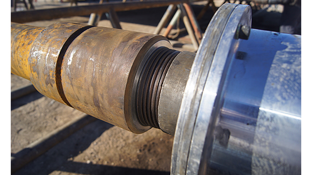
Portable Refacing
- Restore minor galling, dents, corrosion marks, or light scoring on rotary shouldered connection faces so the shoulder can again provide proper metal-to-metal sealing and torque transfer.
- Reduce nonproductive time and cost by allowing multiple light refacing operations in the field before a full re-cut is required in a machine shop.
- The refacing tool is clamped or located on the pin or box so that its cutting/emery surface runs square to the connection axis.
- The operator energizes the electric drive and applies controlled pressure so that only a small amount of metal is removed, just enough to clean and flatten the sealing shoulder.
Quality and limits of repair
- After refacing, the shoulder is checked for flatness with a straightedge and for squareness to the axis, and the remaining material is verified against applicable benchmarks or limits.
- Field refacing is intended only for minor damage; if cumulative metal removal exceeds specified limits or if damage is severe, the connection must be re-cut or reconditioned in a machine shop.
Demagnetization of Ferromagnetic Materials
Demagnetization is required after magnetic inspection because residual magnetism can interfere with both equipment operation and future maintenance or welding quality. Leaving parts magnetized allows them to attract loose metallic particles, which can cause jamming, wear, and contamination in operating mechanisms.
Why demagnetization is needed
- Magnetized parts attract filings, grinding dust, and chips that may remain in housings, bearings, or hydraulic/mechanical systems, increasing the risk of abrasion, sticking, or malfunction.
- In welded or rotating components, residual magnetism can also disturb welding arcs or affect sensor readings in later inspections, reducing reliability and service life.
Typical demagnetization practices
- After magnetic particle or electromagnetic inspections, components are exposed to a controlled decreasing magnetic field (often AC or DC with gradually reduced current) to randomize magnetic domains and reduce residual field strength to an acceptable level.
- Residual magnetism is then checked with a Gauss meter, and parts are only returned to service when readings fall below specified limits, minimizing the risk of attracting debris during operation.
Lifting & Equipment Inspection
Lifting and equipment inspection services ensure safe operation of cranes, hoists, slings, rigging gear, and related machinery in Kuwait’s oil and gas sector through periodic thorough examinations, NDT, load testing, and certification.
Standards and Compliance
Oil/gas lifting inspections follow LEEA guidelines, API specifications, LOLER/PUWER principles, and local KOC/QP requirements, with frequencies of 6-12 months or after repairs. Certifications verify compliance with ISO/IEC 17020, EIAC/ENAS accreditation, and manufacturer specs; records include test logs and traceability.
Inspection Methods
Services cover visual checks for wear/deformation, NDT (MPI, UT) on pins/welds, proof load testing, and functional tests on controls/safety devices. Specialized oilfield focus includes wire rope EMAG, pedestal/offshore cranes, and explosion-proof gear.
Mobile equipment inspection
Mobile equipment inspection in Kuwait’s oil and gas sector verifies the safety and operational integrity of vehicles and machinery like cranes, forklifts, tankers, and earth-moving equipment through visual, functional, NDT, and load testing per LEEA, API, and KOC standards.
Scope and Standards
Inspections cover fuel/water/vacuum tankers, frac units, cementing units, trailers, generators, and mobile cranes, ensuring compliance with international codes, manufacturer specs, and local regulations like KOC HSE requirements. Frequency is typically annual or after major repairs, with digital certification and tagging.
Key Inspection Elements
- Visual/Structural: Frame cracks, weld integrity, tire wear, leaks, corrosion on tanks/chassis.
- NDT: MPI/UT on critical welds, pins, axles for fatigue/sub-surface flaws.
- Functional/Load Tests: Brakes, hydraulics, steering, lifting capacity (125% SWL for cranes); engine/compressor checks.
- Safety Systems: Lights, alarms, emergency stops, fire suppression, DROPS surveys
DROPS Survey & Risk Mitigation
DROPS (Dropped Objects Prevention Scheme) surveys on drilling rigs systematically identify and mitigate risks from unsecured equipment, tools, or materials at height that could fall and cause injury, equipment damage, or downtime. These surveys follow industry guidelines like IADC HSE Section 16, DROPS Recommended Practice, and API RP 54, with independent third-party audits recommended quarterly or after high-risk operations like jarring.
Survey Process
DROPS surveys divide the rig into zones (derrick, substructure, pipe racks, monkey board) for systematic visual inspections of permanent and temporary equipment at height. Inspectors check for loose bolts, unsecured tools, degraded lanyards, and retention failures, using checklists, photos, and a DROPS register to log findings, priorities (critical/major/minor), and closeout actions.
Key Risk Areas on Drilling Rigs
- Derrick/Monkey Board: Top drive, elevators, tongs, spare parts, cameras—must use dual barriers (primary retention + tether/secondary catch).
- Rig Floor/Substructure: Pipe handling tools, kelly, stands, catwalk equipment prone to vibration loosening.
- Pipe Racks/Catwalks: Unsecured tubulars, elevators, slips during roughnecking or rough seas.
- Temporary Equipment: Hoses, gauges, cameras installed without engineering review or lock-wiring.
Risk Mitigation Measures
- Red Zones: Barricade high-risk areas under overhead work; permit-to-work system enforces no-entry during jarring/drilling.
- Tool Lanyards & Barriers: All tools at height tethered (min 2:1 safety factor); secondary catch nets/screens on critical paths.
- Inspections: Daily/weekly rig crew checks + monthly PM + quarterly independent DROPS survey; post-jarring/vibration inspections mandatory.
- Design & Maintenance: Lockwire/Nyloc nuts, DROPS-rated toolkits, equipment registers for temporary installs.